Pages

Monday, June 15, 2015

A two channel mic & line mastering preamp

Not long ago my old friend Paul contacted me. Paul was around when I designed and built the first 4 channel mic pre that was commissioned by a recording studio clear back in 1999. He always encouraged me to finish the project when I got bogged down during a divorce and subsequent irresponsibility. He was there to push me to start building other stuff, like amps, preamps and other things. We've been in touch lately (he moved far away from here) and he asked me to build him a two channel version of the 4 channel studio version that he could use for mastering and as a mic pre for tracking. Basically the idea is to bypass the mic pre's in his current recording chain and inject some 'tube magic' into the path. I was happy to oblige!

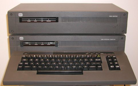
The first order of business was to figure out a box to house it in. I found a surplus site that had tons of stuff and in particular a discontinued product from the early 80's called a NABU Network adapter. It's was basically a method to connect personal computers together in a network using cable TV technology - think of a network adapter that has a channel 3 transmitter / receiver built in (like a VCR). I guess it never took off because IBM came out with a different system that became the industry norm. So there's a warehouse somewhere with thousands of these boxes just waiting to be re-purposed!
http://www.cse.yorku.ca/museum/v_tour/artifacts/artpics/25nabu.jpg

I decided to use a leftover prototype PCB I had made for my previous headphone amp / preamp project (written about elsewhere here) for the basis of the design. I basically adapted the PCB layout to the mic pre schematic I had previously worked out, with a few twists. In building this project I actually found a few better ways of building that mic pre from 15 years ago.. I guess we learn a few things along the way, even if we are old!

The design features transformer balanced XLR (mic) and 1/4" (unbalanced line) inputs, transformer coupled balanced outputs, a 12dB pad and 48V phantom power on the mic circuit. The B+ and filament power supply are fully regulated. The circuit is a two stage design with the volume pot between stages. There is a mic / line switch, a power switch and a bright red LED. The circuit uses 12au7a tubes for gain, one per channel.

I wanted to keep things simple and inexpensive so I tried to use as many parts on hand I could find. I ended up ordering a few resistors, pots, switches and output transformers, in addition to the NABU box. The rest was from the spare parts bins and leftover parts from ESA products. The input transformers are fully shielded in mu-metal cans and are terminated in a 7-pin setup that required special 7-pin sockets. These I pulled from an old TOA mixer that was being thrown out some time ago at my job. (I work in Audio Visual and have to opportunity to 'scrounge' lot's of cools stuff).

It's helpful to know what the front panel is going to look like before laying out the components. I designed the front panel so I could print the wire-frame to scale and use it to layout the hole pattern for the pots and switches. Next is to figure out how to best arrange the internal components for best signal flow and maximum noise rejection. Once I had all the positions marked drilling the holes was the next chore. Unfortunately only a few of the original holes ended up being useful. I'm getting better at laying out and and drilling holes but I much prefer to have the casework pre-punched and finished as with my ESA products. Here you can see the NABU casework with the holes punched and the power supply installed.

For this design I decided to inject the line-in signal to the first stage amp and switch the signals between line and mic with a DPDT toggle rather then using shorting 1/4" jacks as I had done in the previous design, where the line signal was injected directly to the volume control between the first and second stages. Also, I changed the pad value from 18dB on the original to 12dB on the new design. The phantom power supply was also improved; this time I employed a 'floating' regulator - an 18V regulator chip that came with the NABU, floating on a 30V zener, supplied via a voltage divider off the B+ supply.

The circuit design is basic. The mic signal first routes to the front panel for the 12dB pad switch, then to the input transformer where it gets a 20dB boost via the turns ratio. The line input goes through a 6dB pad to insure plenty of headroom and better balance the signal levels when switching from mic to line. Both route to the mic / line switch and then to the input grid of the first tube stage which is a common cathode triode stage with the cathode un-bypassed to increase linearity. The output is capacitor coupled to the volume pot which then feeds the second tube stage, which feeds the output transformers and the 1/4" TRS balanced outputs. Pretty simple huh?


My belief is that simple sounds better, especially when implemented with the best quality modern components and very clean and well bypassed power supplies. The B+ and Filament voltages are just that, very clean and well bypassed. Each tube stage has a trio of low impedance high ripple bypass caps (68uf bypassed by 10uf bypassed by .47uf poly cap) for excellent isolation from the other gain stages and power reserve for impactful transient performance. You can see all the bypassing built into the circuit in the picture above.

As always, things don't go as planned. While testing I found that the original circuit design didn't translate exactly to the new layout. The planned for 12dB pad ended up being more like 40 due to a different mic input transformer primary impedance. The output transformers had too high a turn ratio rendering the output level too low so I ordered some Edcor 15K / 600 line transformers. The original design called for a 500K pot but since the new design has an un-bypassed cathode to improve linearity, the output impedance of that stage is much higher than the original design, which did have a bypassed cathode. This combined with the 500K pot was too high a driving impedance to overcome the miller capacitance of the second stage which rolls off the highs. Changing out the volume pots to 250K alleviated this problem while not affecting the gain much. The 6dB pad on the line input wasn't planned for and had to be added after evaluation. But all in all it went off pretty well I'd say!

Here's a pic of the final wiring. Unfortunately the box can't be rack mounted due to it's 18" width so it won't have 'rack ears' but I'm sure Paul will find a good home for it!


Here's a detail of the input wiring (before I added the 6dB pad). You can see the input transformers:


Here's a look at the front panel switches and pots & associated wiring:


That's all for now but I will add photos of the finished product when the faceplate arrives!

Tuesday, December 3, 2013

BIG IRON - the 200W monoblock monsters!

Not long ago I was contacted by David Counsell of dc10audio to create an amplifier for his company to sell along with his speakers. We collaborated and came up with a few ideas, the first of which was a variation of my 66-100 amplifier using a higher plate voltage and KT-120 output tubes, higher grade capacitors and wiring and a different color scheme. A higher VA rating required an all new power transformer, and a driver stage with more current capacity for those big tubes. This was successfully completed last spring and sold to one of his clients, who is very happy with the amplifier.

At 120 watts / channel this amp took control of the big Martin Logan CLX's at my buddies shop Reference Media in Everett, WA. The sound was big, open, tight and nuanced.

Fast forward a couple of months. David and I agreed to do the Rocky Mountain Audio Fest together and he wanted a super amp, a statement product to go with his speakers- a pair of 200 watt monoblock amplifiers. With the show only a few months into the future and knowing the lead time for such things as custom wound transformers and all new casework, I was  just a bit nervous at this proposition. After some consideration I determined that I could do the project if the 66-100 casework could be used. This would require a modification of the design since the stereo amp has 3 transformers and the monoblocks would have only 2 per unit. The solution was to create a custom aluminum top plate to cover the mounting holes for the stereo version, while at the same time dressing up the appearance of the amplifier and stiffening the chassis to accommodate the larger transformers.  

The first thing I needed to do was to order the custom output transformers so that I could build up a prototype and prove the design. Since my usual supplier doesn't make a power transformer above 350VA or an output transformer above 100W I had to find another vendor. After some internet searching and sending quote inquiries, I found a company that would wind the output tranny's. The power transformer was covered since I had already found a local commercial supplier that could build what I needed for the 68-120 project. I just had to specify a larger core size and higher VA rating to match the new output transformers.

So it all came together, the BIG IRON arrived and I was able to build one mono amplifier prototype that easily made 200W into 4 ohms with 4 6550's. (It would make 240W with KT-120's but 200 watts is enough power for most people and the 6550's sound better anyway, at least in this design.) The next step was to create a parts list based on that design; specifying the best parts for their respective applications while trying to insure they won't be discontinued can be a challenge. Over the years of doing this I've had to scramble to find replacement parts for those which had been discontinued more than once.

David wanted to incorporate some high-end wire and capacitors for this build so I used silver / teflon for input wiring, silver plated copper / teflon wires for the output transformer secondary leads. All other circuit wiring is point to point on the component level and signal carrying interconnect wires are silver plate copper / FEP. The capacitors ended up being the Jupiter beeswax / paper line and took a few weeks to arrive. These I ended up bypassing with some small value polypropylene film and foil caps, which improved the focus and tightened up the bass somewhat. We also used some really nice rhodium plated binding posts that cost a fortune. Here's a shot of the interior wiring during construction.

This design is merely a single channel of the 66-100 on steroids. Instead of 2 6550's producing 100 watts there are 4 6550's pounding out 200. The driver stage took some consideration- the drive requirements would be a challenge especially at high frequencies where the miller effect of the power tetrodes will cause distortion and attenuation. At first I explored a differential pair with cathode followers but thought the layout would be too complicated. I like to keep things simple so I just paralleled the two triode halves in each driver tube and tied both composite tubes together at the cathode thus creating a 'super-tube diff pair' (I could use that in marketing..). So essentially each parallel triode pair drives two paralleled 6550's for each half of the output tranny's primary. Got it? It worked like a champ! Of course this amp retains all the features found in the 66-100 like cooling fan and individual bias pots for each output tube and a built in meter for setting bias, and design features like local feedback in the output stage and optimized concertina phase splitter. Look at the huge PSU reservoir caps and the smoothing choke, also found in the 66-100.

So as Murphy would have it, what works great in prototype has issues in the final build. I spent a considerable amount of time chasing down frequency response aberrations, ringing and such. I experimented with the feedback level (very little loop feedback), compensation caps in the driver stage, replacing those beeswax caps with poly's, etc. Then I noticed that the response was nice and flat when the amp was open on the bench, but when the cover was grounded to the rest of the chassis the response had a rise in the high frequencies. Very strange. Turns out that the output transformer's core doesn't like to be grounded but there's no way around that! I ended up using a simple zobel network across the primary.

Here's the frequency response and THD plots at 200W into 4 ohms. The THD measurement shown is 1.6% @ 1kHz. Note the flat distortion spectrum above 40Hz. Below 40Hz the distortion rises due to transformer core saturation. This is pretty good for full output! But who listens to music at 200W?

 Here's the plot at 25W - .5% @ 1kHz.

Notice much less low frequency distortion in this plot. 25W is pretty much the most average power you need but having 200W in reserve gives you much more headroom and potential dynamic range.

Here's the 3W plot - .3% @ 1kHz. This is where most of your music lives. And this is why these amps perform so well even on high-sensitivity speakers.


So you're wondering how it all sounded? Very much like the 66-100 but more power, a little more liquidity and finesse. I attribute this to the upgraded wiring and caps, and of course the output iron is different as well. All of these things add up and contribute to the overall presentation that an amplifier will give. But the fact that it's so similar to the 66-100 is due to the circuit topology and layout itself being mostly the same. Hard to improve on an already proven design!

David was thrilled at the show and we had very good response to the sound in our room but that's another story..


These were built exclusively for dc10audio and carry their branding. They are available directly from their website: http://dc10audio.com/. They make some very nice high-sensitivity speakers, which happen to mate very well with ESA products~

Here's a shot of our setup at RMAF:
The speakers are very interesting - the tweeter horn doubles as the reflex vent for the woofer, and they incorporate a tone-wood resonator panel that damps internal vibrations while creating a passive radiator effect. The sound is immediate and refined and the overall bass response is incredible. You really have to hear it to understand - they don't sound like your typical high-end speaker, they sound like music. Lovely.

If you look closely you will see the ESA 66-001p Vacuum Tube Reference preamp. A new preamp was planned for the show but we ran out of time to get it all built and dialed in so the ESA unit was used to very good effect. Stay tuned for another post on the development of the new preamp, which uses circuit boards instead of point to point in an effort to cut down on labor.


Happy Listening!


Tuesday, February 5, 2013

Prototype Headphone Amp continued..

It has been quite a while since my last post on the prototype headphone amp, seen above. I built this up for the folks at Reference Media for a possible product launch that never happened, sadly. So, it's been sitting on the shelf for about a year now and I decided it was time to do something with it!

While visiting my brother earlier this month I noted how he is SO into music but really doesn't have anything decent for play back. Because of his situation he listens mostly with headphones so I decided to build him a handy dandy headphone amplifier. But, I needed a box or case to put it in, and to make a few decisions on functionality.

First, the functionality aspect of the design. The basic circuit can be adapted to serve many functions being set up as two gain stages separated by a volume control. I decided to make it more flexible than a straight amplifier by providing three inputs, a selector switch, defeat-able line outs for driving an amp (or powered speakers), a power switch and pilot light. A little less functionality than the 66-001 preamp; no balance control or mono switch, and less input options. With that figured out I could go shopping for parts, scavenging whatever I could from my spare parts collection (ever expanding I might add).

For the casework, I knew that the power transformers would be on-board (unlike the 66-001 series of products which have external regulated supplies), so I would need to find a box big enough to house everything. We have a local PC recycle place that has all sorts of discarded electronics for relatively cheap (though lately they have put ridiculous prices on some real junk) where I found an old Avid 888, an 8 channel 48K Pro-Tools interface from the '90's for $15.00. Perfect! Just need to drill a few holes, fill in a few more and do a custom faceplate.

Every project I do has a phase where I just sit and stare at it for a while, trying to figure out where everything will go. I ended up arranging it in a logical fashion; power transformer on the left side of the chassis because that's where the IEC AC inlet filter and fuse are mounted, PCB and output transformers to the right, with the OPT's in the rear near the output jacks. Next I had to fill the holes in the rear panel - 24 XLR sized holes that is! I happened to have an 18 gauge painted steel panel left over from something. It would need to be cut to size with holes for RCA jacks drilled into it. A few minutes with my angle grinder w/ cutoff wheel and drill press took care of that. I laid out the hole pattern for the circuit board, drilled and installed it with 4-40 screws and nuts, using nits as standoffs as well.

So far everything has been sourced from my spare parts but I needed some switches, knobs and jacks. That would come later, but for purposes of testing I wired in temporary jacks and fired it up. Having decided to change the tubes from ECC99's to the more common 12au7a's meant that some circuit parameters would need to be tweaked to gain best performance. Knowing that the max level it will probably ever see is 2Vrms from a CD player or DAC (ridiculous high level IMO) I ran some sweeps at that level to gauge the distortion. Not so good. Looks like the input stage would need more headroom, or higher plate voltage. No problem, I removed the PSU dropping resistor for that stage and wired in a 5K pot. This way I could adjust the pot, monitor the plate voltage and do sweeps to check distortion at different settings, keeping the plate and cathode resistors constant. It turned out that the best setting increased the plate by about 25V; the 4.7K dropping resistor was replaced by a 1.8K resistor. As you can see from the final sweeps the distortion is below 1% across most of the audio bandwidth, and is dominated by 2nd and 3rd harmonics, the higher order stuff down in the noise floor.The increased distortion at low frequencies is due to the output transformer saturating but at low frequencies our ear is less sensitive to distortion. Higher up the distortion remains fairly constant with frequency which is a good thing.

The distortion readings shown are at 1kHz. The top trace is the sweep and shows the frequency response, the black trace is THD, the rest of the traces are 2nd, 3rd, and higher harmonics (see legend at bottom of graph). The right channel shows slightly more distortion; this is due to differences in the tubes, which are never matched perfectly and are the biggest variable in designing tube circuits (modern passive components are pretty stable and precise in value). But the overall distortion in the right channel is at .321% THD, well below the theoretical 1% threshold of audibility.
Shown above is the frequency response. Not bad for a transformer coupled tube amp! The transformers are actually 70-volt speaker transformers. These work great for tube driven line stages because of their high impedance ratio, and you have your choice of impedance taps too. Though they're only designed for about 50Hz to 15kHz in their intended application, the fact that they're not being driven more than about 1/2 watt into headphones pushes their bandwidth to full spectrum. They have the added benefit of very low output impedance- in this circuit about 10 ohms; great for even low impedance 32 ohm 'phones which are the most common these days. And into higher input impedance's typical of an amplifier (10K and above) they perform even better, able to drive long interconnects with no HF roll-off. Plus, in my opinion, transformer coupled circuits have a richer, more harmonic and punchy sound.

So now everything is finished, tested and tweaked, ready for the faceplate. Below is an image of what that will look like, it's about a week out as of today.
This turned out to be a fun little project! And hopefully fun for my brother, too. Here's the final look with the faceplate~

Sunday, July 29, 2012

A cool new headphone option!

I haven't been on here in quite some time but something happened today that I have to tell you about (if there's anyone who's looking..). An acquaintance of mine from church told me about a new venture he's embarked upon. He and his friend found that the market for quality headphones that the younger generation could afford was seriously lacking. So they decided to do something about it, namely, start their own headphone manufacturing company. Right up my alley! He brought over a pair for me to audition on my tube gear and let me just say that I was very impressed. They have 3 models currently; ear-buds (in ear type) called 'The Olympia', a smaller over the ear called 'The Shasta' and a larger over the ear set called 'The Teton'. Now the thing that sets these headphones apart from their immediate competition is the fact that they are made of wood. The ones I listened to were the Shasta, which have a bamboo body. I have Sennheiser HD448's as a reference and the Shasta's sounded very close. Excellent bass, both in quantity and quality, the mids were clear and the highs were a shade brighter than the HD448's, which isn't a bad thing. The overall build quality was high, especially for the price point. The cable if OFC and has the same rubbery jacket that my Sennheiser's have. Another cool aspect to these phones is that the cables unplug from the cans; there's a standard 1/8" mono jack on each ear cup and the cable is terminated with 1/8" gold connectors. One could easily DIY some great headphone cables! Not that the stock ones are lacking in any respect. Another feature is that they fold up, and the quality of the plastic is really nice, with the soft rubbery touch found in many automotive interiors these days.

Here's the one's I looked at. They're quite handsome for $55.00! I can't wait to hear the Tetons!

Here's a link to their website: http://www.rikaheadphones.com/


The price for these cans is almost free considering the quality. Get a pair for yourself and a pair for your teenager's ipod, and start a new generation of people who appreciate good sound, not just a flashy skull logo.

Thursday, July 7, 2011

Prototype headphone amp

The folks at Reference Media encouraged me to create a new series of lower priced, easier to assemble products that they can sell at their stores. This prompted me to re-consider my stance on printed circuit boards (PCB's). I still believe that they are not good for tube circuits because of the high-voltage and heat involved, and the capacitive properties of the board itself, but if designed and implemented with care they can work just fine. After all, most of the other tube manufacturers out there use PCB's. The new series will use PCB's for ease of construction, have simpler casework with silk screened front panels (instead of engraved) and integrated power supplies (instead of external).

The Sixty-Six Series (66-100 power amp, 66-001 preamp and derivatives) represent the premium products that we produce and will remain unchanged; full point to point wiring, external power supplies for the preamplifiers, engraved front panels, more robust and complex casework. I still believe that point to point is superior for tube circuits and sounds more transparent, and allows for optimum circuit component layout since it's three-dimensional. The lower priced series (yet to be named) will retain the same parts quality and circuit design but at lower price points for reasons stated above.

So, the first foray into this new paradigm is a headphone amp. The circuit is a virtual copy of the 66-001 line stage, minus input selector, balance, mute and mono controls. The original 66-001 preamp started out as a headphone amplifier that I breadboarded up several years ago and found to be an outstanding preamp. So it was a no-brainer to make a headphone amp out of this circuit.

The amplifier and power regulator circuits will live on the same PCB. This same circuit board can be adapted to a full blown linestage with some changes in casework and the addition of the requisite switches, pots and jacks. This allows flexibility and further reduces costs. It has stereo unbalanced inputs and parafeed transformer coupled outputs. There is a low/high gain switch that switches primary windings on the output transformer to accommodate differing impedances and sensitivities and should drive most any headphone out there. Each amplifier stage has multiple bypasses on the power rails, which is regulated, along with the filament supply.

Many hours were spent up front designing the circuit board, drafting the casework and specifying parts that will fit. This process resulted in me finding better parts that will be carried back over to the Series Sixty-Six products.

As with all PCB's I've designed, there were things that didn't quite fit, and a few mistakes. That's the way it goes; you never know until you get that first one and start loading parts. It's a process, but now all the corrections are made and the prototype is built. Not without a few mishaps! I had to replace the high-voltage regulator mosfet (4 different times!), because of shorting it out while measuring the rail voltage. The meter probe kept slipping off a resistor leg. Bang! One thing about PCB's- the parts are hard to remove once they're soldered in place.
In the photo you can see the two output transformers in front, the PCB mounted volume control and the large poly coupling caps. Further back are the tubes and related amplifier circuitry and at the rear of the board is the PSU regulator circuits. Outside the picture are the two power transformers. Of course this will all fit into a box about 12" wide by 10" deep and about 4" tall. The tubes will stick out the top of the box, which will have plenty of vent holes.

Playing back high-res flac files from my computer's external soundcard and driving my Grado SR80 'phones, the sound is wonderful, in fact, it sounds just like the reference 66-001 preamp upstairs in the living room..

Stay tuned for progress on this new product development. Next comes the casework and the revised PCB.

Saturday, February 26, 2011

My visit to Reference Media

The Elliott Studio Arts 66-100 in a showroom!


I recently ran into my old associate Hans at a 7-Eleven. After a brief visit I found out that he works at the only high-end audio shop in Everett, WA; Reference Media (they also have a store in Bellingham, WA) http://www.reference-media.net/. I told him about my amp and preamp and we agreed on an audition of the 66-100 the store. I was surprised when I drove up and saw the store front, very nice. The inside is very well appointed with tasteful local art on the walls, a nice color scheme, wood floor and high ceilings. I was greeted by a McIntosh / Martin Logan system sounding sweet. The also stock Marantz, Peachtree Audio, Shunyata Research, Sonus Faber, Vienna Acoustics, Focal, ProJect turntables and more. In the picture below, up the stairs you can see the Golf Simulator system they sell set up for demo. Hans took a couple of swings to demonstrate, it's pretty impressive! You use real golf clubs and balls, driving them straight into a specially made screen. You can choose your course, the weather and wind conditions, etc. Neat. I got the grand tour, they have plans to install a dedicated theater room, build out some unused space for offices and divide up the main floor sales area into listening rooms. The store has a friendly atmosphere and the staff makes an effort to be helpful, informative and never snobby or pushy.
So, on to the main event. The first system we used to evaluate my amp was based on the Peachtree Audio iDecco as a preamp, driving the Focal Chorus 706V speakers. Cabling by XLO. Promising. Good sounding speakers, Hans said my amp tamed the tweeters somewhat, though you could still hear all the detail, and made them more enjoyable.

Next up on the same system were the Sonus Fabers, picture on the right. Not sure exactly which ones, probably from the Toy Collection. They were little towers w/ two 5" woofers and a tweeter. The sound was wonderful; rich, detailed with more bass than the last set of speakers, great imaging. But the best was yet to come with this setup. On the left is the Vienna Acoustics Mozart Grands being driven by the ESA 66-100. This was by far the best sounding speaker in this setup. Sublime.


OK, now on to the BIG system! McIntosh MCD500 CD player, McIntosh C2300 preamp and ESA 66-100 into the Martin Logan CLX's, with the Shunyata Hydra power conditioner. WOW! And especially wow when the volume was raised up. The amp drove them perfectly, taking control of the huge bass panels like nobodys business. The midrange had that tube realism and the highs were perfectly rendered. A very good match! It certainly helps having a good source and preamp to show the full potential of this amplifier.


All in all an enjoyable visit and a great opportunity to see one of my designs mated with some high-end speakers and equipment, and to confirm that it is indeed in good company - a true high-end product. And a great store to experience the high-end in comfort!
When I retuned home after exposure to all that high-end gear I was not dissapointed with the sound of my own system, consisting of ESA 66-001p Preamp, ESA 66-100 power amp (prototype), Rega Apollo CD player (modified), Thorens TD125 w/ MMF 5 tonearm and Klipsch RF83 speakers (modified). Listening to Pink Floyds incredibly detailed and layered recording, Momentary Lapse of Reason, on vinyl was re-affirmation that I have, indeed, achieved high-end sound in my own home.
Now that's what this is all about!

Sunday, December 12, 2010

Birth of an Amplifier

Here's a short description of the construction of an Elliott Studio Arts 66-100 power amplifier. This is a basic model, unbalanced and without a triode/UL switch (which switches the output stage between modes). The first step in construction is to assemble the chassis and related components. Shown below is the top panel to which the circuit board is installed after it is seperatly constructed, as well as the power and output transformers. A horizontal brace can be seen, situated below the heavy transformers to provide additional strength, and a lightweight vibration damping material is applied to damp rining. The tubes, bias pots and switch protrude through the holes and the bias meter occupies the rectangluar opening in the center.


Next you can see the bottom of the chassis with the seperate front and rear sub-panels installed. Seperate sub panels facilitate changing the configuration without having to re tool the entire enclosure. In example, the rear sub panel for the balanced version of the amplifier is different but is the only part that needs to be changed. This makes the product flexible and economical to build in small quantaties. Also seen is the cooling fan, input and output jacks, power inlet / filter and fuses. Up front you see the main filter caps, smoothing choke and power switch. In the center is the terminal block where all the power wiring will land when the top panel and circuit board are installed.


The next picture shows the circuit board with the tube sockets, terminal strips, bias meter & pots, and ground wiring installed. This "circuit board" is actually 16ga. steel which provides a rigid backbone for the circuit to live and an active ground-plane with good RFI rejection. All the components are riveted directly to the circuit board and will not vibrate loose over time. All the wiring is point to point just like the old days. This method of wiring is time and labor intensive but is more robust, superior for the high-heat and high-voltage environment of tube amplifiers, and sounds better. I have repaired some contemporary tube amps that use printed circuit boards and have seen catstophic failure of the board itself where the heat of a power resistor actually burns a hole through it. No way to fix that without replacing the entire board! Printed circuit boards also exhibit small amounts of capacitance between traces and the board material itself is not a very good dielectric, which can smear the sound to a degree. That said, we do use printed circuit boards in non-critical areas, like power supplies and logic circuits.

Here things are beginning to come together. This is part of the on-board power supply bypassing for the output stage. Also seen in the background is the filament supply circuit with damping resistors and +50V injection to cap off hum and prevent too high a voltage differential between cathode and filament at the input stage phase splitter. Heat resistant ceramic tube sockets are employed for long life and no arcing. All signal path junctions are soldered with silver content solder and care is taken at every step to ensure solid connections and future serviceability.

The next picture shows the input stage under construction. Each half of the input tube (12au7a) is bypassed to prevent power supply interaction between stages. The first stage is a simple voltage amplifer with feedback from the output transformer injected at the cathode, which is bypassed with high-quality solid polymer electrolytic caps. These have outstanding low impedance and ESR properties and live well in high-heat environments. This stage is direct coupled to a spit-load phase splitter which has a build-out resistor in the cathode leg to match output impedances of both halves for better high-frequency linearity.


In this picture the input stage / phase splitter and driver stage are completed. In a novel implementation of local feedback and bootstrapping this little stage delivers the needed voltage swing to drive the output stage to full power at low distortion. One wouldn't normally consider the 12au7a to have the balls to do this! High-quality polypropelyne coupling and bypass capacitors are used throughout. All wiring is high-tempature and rated for applied voltage.


Here's the completed circuit board installed to the top panel with transformers mounted and wired into the power supply circuitry, which can be seen along the bottom. On the left is the main B+ supply, on the right is the bias supply and filament damping circuit. Off to the side can be seen a small printed circuit board which houses the 60 second B+ delay, which allows the filaments to heat up fully and applies the bias voltage before the high-voltage hits the tubes. The output stage employs an LR network to equalize the small inductance differences between windings in the output transformers. This also improves high-frequency linearity.


Speaking of transformers, all transformers used in Elliott Studio Arts products are custom wound to our own specifications by a well respected company based in New Mexico, Edcor Electronics. The excellent sound quality and bass control of these amps can in large part be credited to these transformers. The power supply transformer is massive with ample power regulation; in conjunction with the big computer grade caps and choke provide huge power reserves which greatly increase dynamic impact and slam. The power supply is very clean and well protected with fuses and inrush current limiters, which can be seen below mounted to the terminal strip in the bottom chassis.


The top cover and circuit is now wired to the bottom chassis, the input connections have been wired and the output transformer secondaries are hooked to the speaker jacks.


The next step is to install tubes, connect meters to monitor B+, bias and filament voltages and an O'scope and dummy loads to the output. Now fire her up!


After everything checks out, the bias is increased until the proper current reading is applied to each tube, voltages are checked again. Once everything stabilizes it's time to throw some sine waves at it and check for oscillation, frequency response and max power output. Then a complete battery of computer generated tests including frequency sweeps, distortion and square wave response is done and documented for record keeping.


The face plates are installed after all the testing is complete. The amp is then installed in my reference system for a week to burn it in and listen for any anomalies. It is then packaged up and shipped to the customer for many years of happy listening!